Building a LoRa Sensor Node That Holds Range Across Temperature and Weather
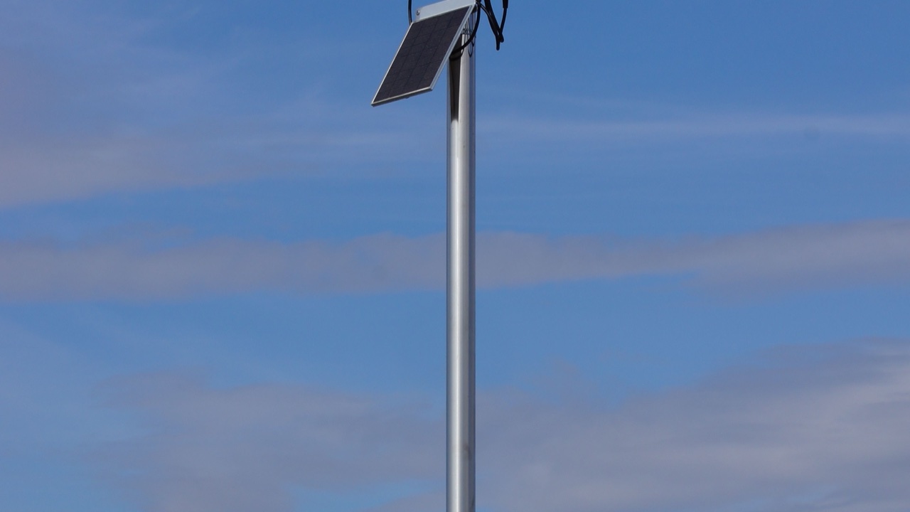
A LoRa sensor node that works reliably on the bench is a starting point, not a finished product. The bench is climate-controlled, static, and forgiving. The field is none of those things. Temperature swings, condensation cycles, UV exposure, ice loading, wind vibration — the outdoor environment stresses wireless sensor hardware in ways that don’t appear in any datasheet test and don’t show up until the node has been out there long enough for the degradation to accumulate.
Getting a LoRa deployment to maintain its range across seasons and weather requires thinking about antenna system durability as carefully as the RF specifications. Most of the range losses I’ve seen in field deployments over time weren’t caused by software bugs or configuration drift — they were caused by the gradual physical degradation of antenna connections and housings that seemed fine when first installed.
How Temperature Affects RF Performance
Electronics specifications typically cover a temperature range like -20°C to +70°C, and most LoRa modules stay within their RF parameters across that range. The antenna and feedline system is less stable.
Coaxial cable has a center conductor, a dielectric, and a shield, each with different thermal expansion coefficients. As temperature cycles, these materials expand and contract at different rates. Over hundreds of thermal cycles — which a deployed sensor node accumulates across seasons — this differential expansion works on connector interfaces. The mechanical preload that holds a connector pair in secure electrical contact loosens incrementally. The contact resistance at the interface increases. The insertion loss at that connector rises.
For a node operating close to the sensitivity limit of its gateway — which is exactly what long-range LoRa deployments aim for — even 1 to 2 dB of connector degradation narrows the link margin to the point where the node starts missing packets in conditions that previously worked fine. The failure mode is gradual and direction-dependent, which makes it easy to misattribute to RF environment changes rather than hardware degradation.
The fix is mechanical: connectors that are properly torqued (finger-tight is not torqued), weatherproofed with self-amalgamating tape, and chosen for outdoor-rated contact materials rather than indoor-spec parts. For permanent installations, N-type connectors are preferable to SMA for their superior weathering characteristics. SMA connectors are workable with adequate weatherproofing but require more maintenance attention.
Condensation Inside Enclosures
Moisture inside an electronics enclosure damages RF performance through two mechanisms: direct corrosion of metallic contacts, and dielectric loading of the antenna if the antenna or its feedpoint is inside or adjacent to the enclosure.
The condensation risk is highest in enclosures that aren’t truly sealed — IP54 and IP65 ratings prevent rain ingress but don’t stop the breathing cycle that happens as temperature changes. Warm air inside an enclosure contains water vapor; when the enclosure cools at night, vapor condenses on the coldest internal surfaces. Over time, this deposits moisture even in enclosures that have never been submerged.
Desiccant packs inside the enclosure extend the time before moisture accumulates to damaging levels. The desiccant needs to be replaced periodically — once saturated, it provides no protection and can actually hold moisture against internal surfaces. Silica gel with a color indicator (blue when dry, pink when saturated) makes it straightforward to verify the desiccant state during routine maintenance without specialized equipment.
For enclosures housing radio hardware, cable entry points are the primary moisture ingress path. Cable glands that were adequately tight at installation become loose as the cable they grip cycles thermally. Periodic inspection and re-tightening of cable glands is unglamorous maintenance work that has significant effects on long-term reliability.
UV Degradation of Antenna Components
UV exposure degrades plastics and elastomers over years of outdoor installation. The effects vary by material: polycarbonate yellows and becomes brittle, standard PVC jacket cracks, neoprene seals lose elasticity. For antenna systems, the practical consequences are cracking of cable jacket (allowing moisture ingress), hardening of weatherproofing tape (losing its seal), and embrittlement of plastic radome elements that protect antenna elements.
A lora antenna specified for outdoor use should have UV-stabilized materials throughout — fiberglass radome rather than standard plastic, UV-stabilized jacket on any associated cable, and outdoor-rated elastomers in any gaskets or seals. The material specifications matter more for a five-year field deployment than for a three-month evaluation.
Cable runs that can be shielded from direct sun exposure — routing through conduit, along the shaded side of a structure, inside an enclosure for as much of the run as possible — extend cable life considerably beyond equivalent runs in full UV exposure. This seems like marginal optimization but compounds significantly over multi-year deployments.
Wind Loading and Vibration
Wind generates two distinct stress modes on antenna installations: quasi-static loading from sustained wind pressure, and dynamic loading from vortex-induced vibration. The quasi-static loading is the one that gets attention because the failure mode — a bent mast or a blown-down antenna — is obvious. The dynamic loading is less visible but potentially more damaging to long-term RF performance.
Vortex-induced vibration causes a whip antenna to oscillate at its resonant frequency in moderate wind — this is the “singing” that pole-mounted antennas make in certain wind conditions. The oscillation imposes cyclic fatigue stress at the antenna base connector and at the cable strain relief. Over enough cycles, this fatigues the solder joint at the connector center pin or cracks the cable jacket at the bend point where strain relief ends.
Fiberglass whip antennas fail at the base connector from this mechanism far more often than from direct wind loading. The failure isn’t a visible mechanical break — it’s a progressively worsening electrical connection that looks like range degradation before it looks like a hardware problem.
Installing antennas with adequate strain relief, using coiled drip loops in cable runs to absorb vibration, and choosing mounting hardware that doesn’t allow the antenna base to rotate or twist under wind load are the practical interventions. For high-vibration environments — rooftops, open fields with consistent wind exposure — shorter, stiffer antenna types fare better than tall flexible whips regardless of gain specification.
Setting Expectations for Field Lifespan
A LoRa sensor node designed and installed with outdoor durability in mind can maintain its RF performance for five or more years with minimal maintenance. A node assembled from indoor-spec components and installed with inadequate weatherproofing typically starts showing degradation within one to two years, and the degradation often appears first as range reduction rather than complete failure — which means it can persist undetected across a large deployment before anyone notices how many nodes have quietly moved from reliable to marginal.
The design choices that determine this outcome are made before deployment, not during.